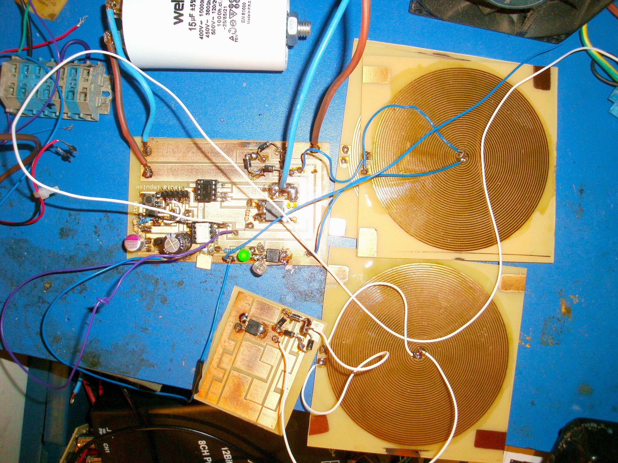
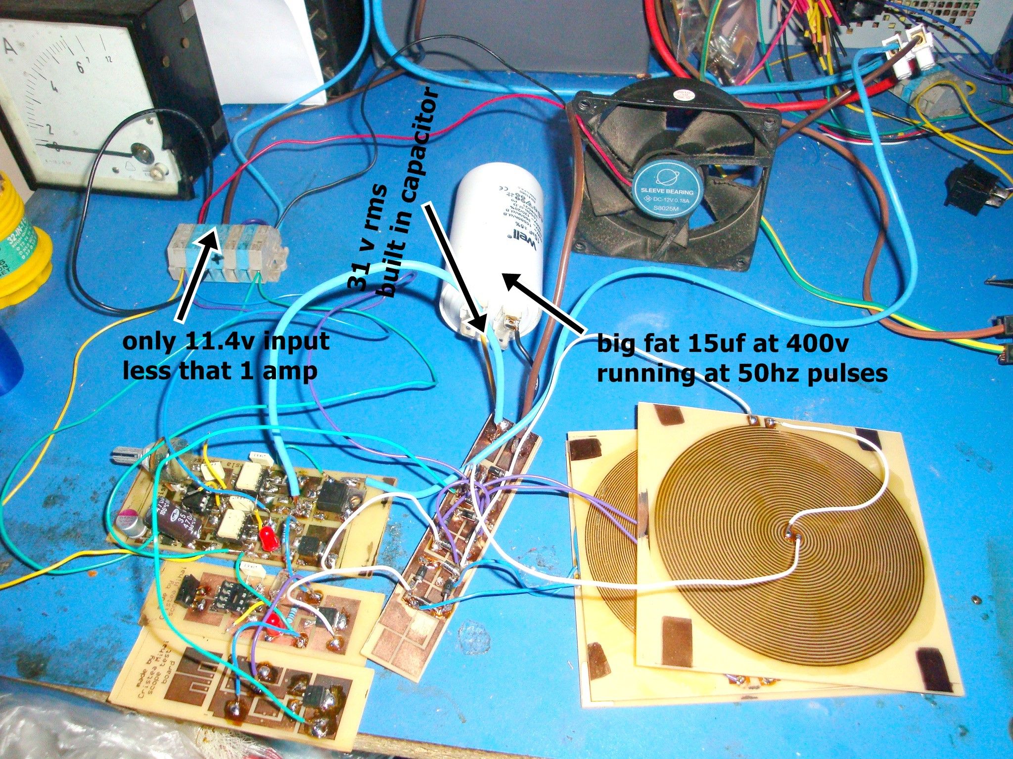
I could not express my indignation and also my joy when i found that i got all wrong. Reading a few passage from J Bedini and Tom Bearden book, i realise that i should not seek more more capacity to dump in to the battery, but ONLY POTENTIAL. It usless to increase the amount of enery that you collect from coil. The inverted circuit only throw the free from charge potential. If i want more power i should increase the peak af voltage and the number of pulses, because the battery only needs the high voltage discharge , the rest will be done by ions. So i think that an 15 uf Capacitor at 50hz will be suitable for keeping 30 V at 50 pulses per second. I will ilustrate my point with following picture.
I will see the effect on bigger battery. The next step i shoud follow is to find the resonanace frequency at those coil. Is very difficult to do that because i need a function generator and a good probe for oscilloscope. I will buy a probe 10 times and i will be able to see what is going on on battery and in capacitor. But my guessing seems to be correct. I curently run the cols at 30khz, i should push to at least 100kz but i dont know if fets will work at that frequency. Any way another limitation that i have is that my fet driver supports only 33 vdc, so the difference between cap and batt in free floating should not exceed 33 v. In my currently project i can go with 10 volt more, meanning that i will have 42 volt on cap. Immagine how much power will be at 300vdc. I will think in future at this. Well another posiblity is to not to increase the voltage but the number oof impulses. Lets say 100hz. But, will this cap whitstand more frequency? Lets try it shall we. For now I will focus on battery response to such many impulses.
i would like make some observation here. Every time after i disconnect the charging module, and conect after a while te voltage increase at maximum charge level. Afer that, it is dropping at normal charging voltage. That means , the battery when stays off charge , inside, the ions are still moving for charging battery. I think what Bedini said that the battery will develop some local conditioning vacuum, as its draw its own potential to recharge. Anyway i owe you guys some scope pictures to see my modification.
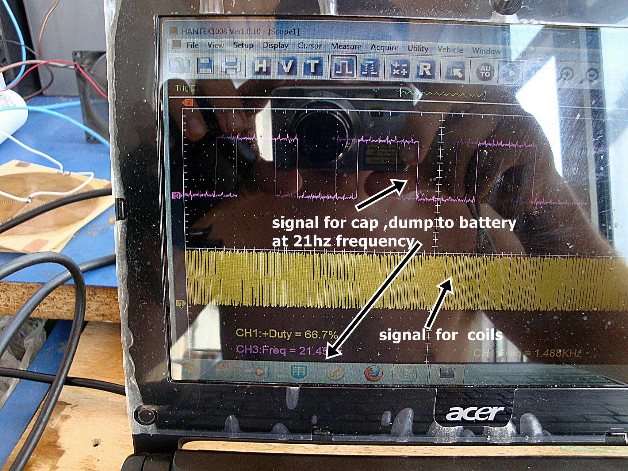
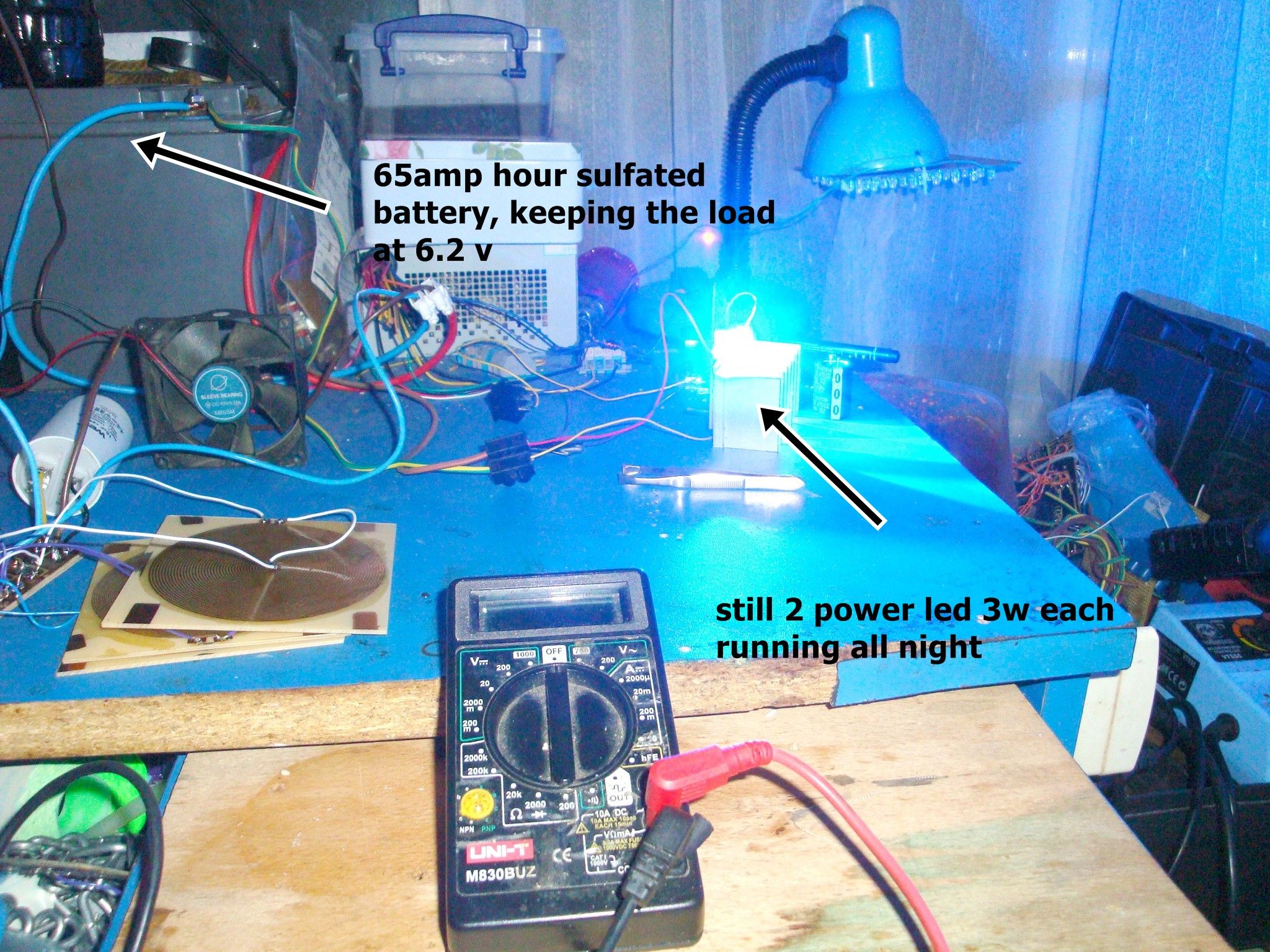
As you see i was wrong about 50 hz for cap. It is only 21 hz so is room for more energy to dump to the batt. I will increase the duty cycle of signal to coil. My purpose for ll this is to charge fast the batteries , and believe me it is charging fast. I ran the power led all night, worked great, no intensity fall.
For some reason ,the input voltage was dropping at 10.8 v, the battery is still charging, so until your input drops under 5v the battery continue to charge. This is amazing as with solar panel you can charge even at cloudy days. I think this will be one great charger and conditioner for battery. Still requires some more test, with big battery and with soar panel. Its kind an expensive to buy even a 30w solar panel.
Investigating more ive reach at conclusio that my charger ca work with only 1 coil, for the fact that i seek only potential. So hitting the inside battery ions is the main target. For that i need only charge sufficient high the cap and discharge on batt. I want to reach 300 volt to see what will happen. For that i have to modify the mosfet driver, i will use h11d optocupler that work at1 kv.
Still, right now with 40 volt peak on cap i can charge a 100ah batt with miliamps. And stll need a soar panel. In the near future i will sell one module charger, for you can use on different type of battery with different type of energy input. i will make an page for that
I will make a chapter here , as is very important in my project.
Releasing the beast
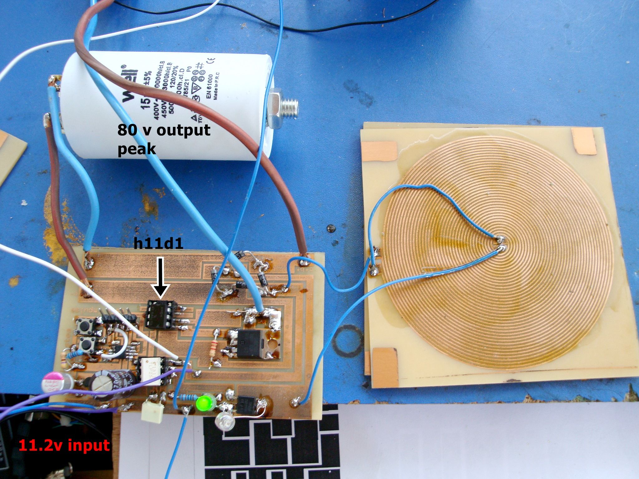
Ive made some sacrifice to get here, i burned all my fet driver, because ive increased the voltage in the cap. So more voltage , more potential you will add to the battery. When i reached 80 v peak my mosfet driver was burned up. That was not surprise for me but was a lost to me , as that fet driver is hard to get. anyway i change all configuration and i added instead an high voltage optocupler H11d1. I made a new board, and i added some improuvement in architecture that is easy to solder. Here it is : The system is dumping to battery almost 90V, but with deaceasing timer. Battery feel that and responds by quickly rise and fall in voltage.
Finnaly i have reached the 100 peak volt in cap. Ive added one module , thus input power increase no more than 900mA. I will not seek more power but i want to try how the sistem works with solar panel.